
This evening I made a start to build the tortoise robot. Here a brief description of my findings
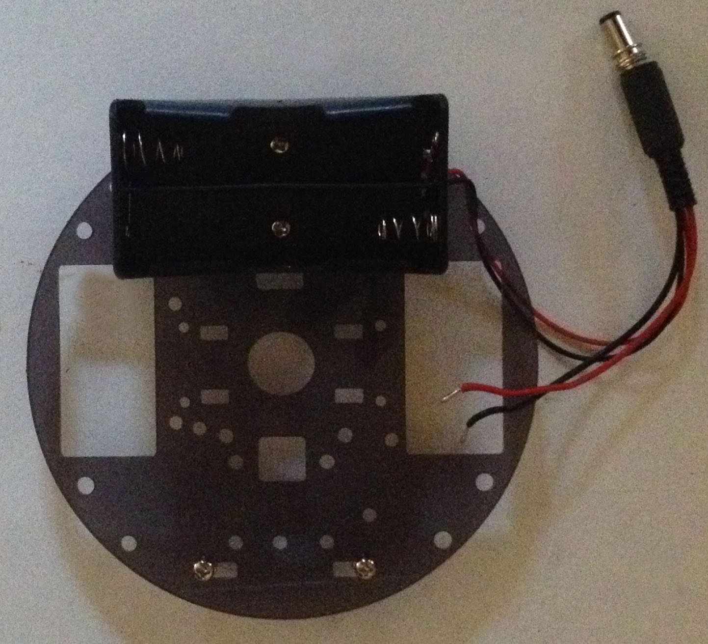
I started with tearing off the protective file on the perspex plates and started mounting the 4 (3x18mm) screws for the roller balls, each screw is secured with to nuts. Make sure you pick the correct plate, because they are not equal.

Next I mounted the battery holder using 2 (11 x 3 mm) screws and nuts, notice the ground plate is not symmetric.
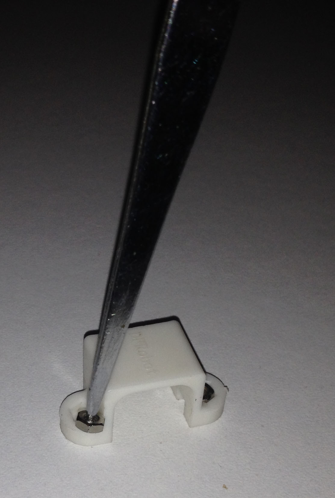
First mounted the two motors, usign the two motor holders and 4 4 (12x2mm) screws. I took some time to get the nuts into the motor holder, the easiest way was to use a pair of tweezers and putting the points into the 2mm nut, due to the tension of the tweezers the nut could be placed into the motor holder.
I also mounted 2 short (10 mm) standoffs on the bottom side for the optical sensors, using 2 (8 x 3mm) screws

Then mounted the two (18x3mm) screws, each secured with two 3mm nuts, for the motor controller board
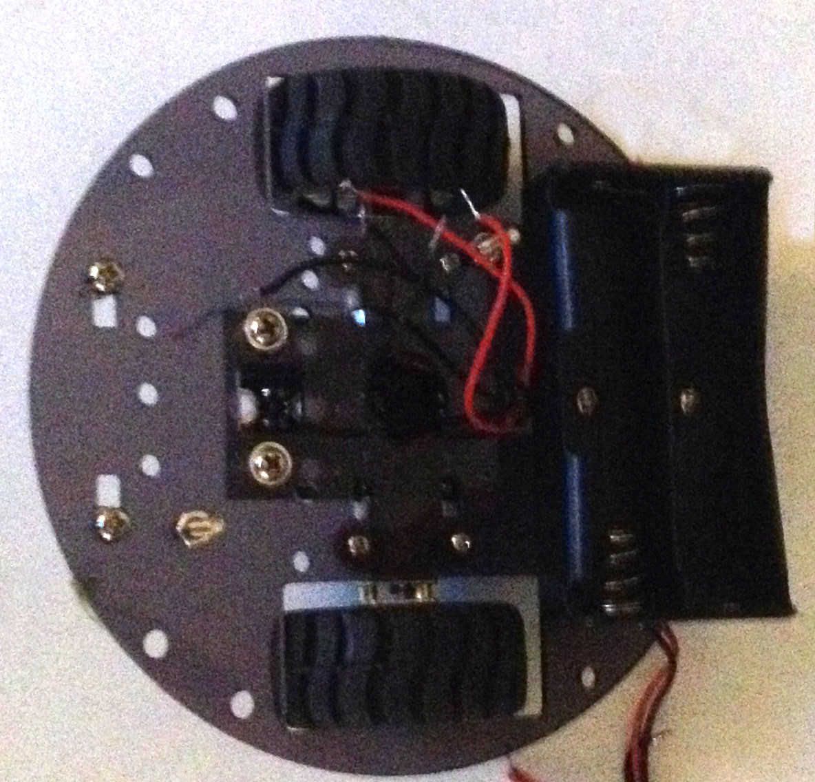
The next step was mounting the optical sensors using two screws (10x3mm)

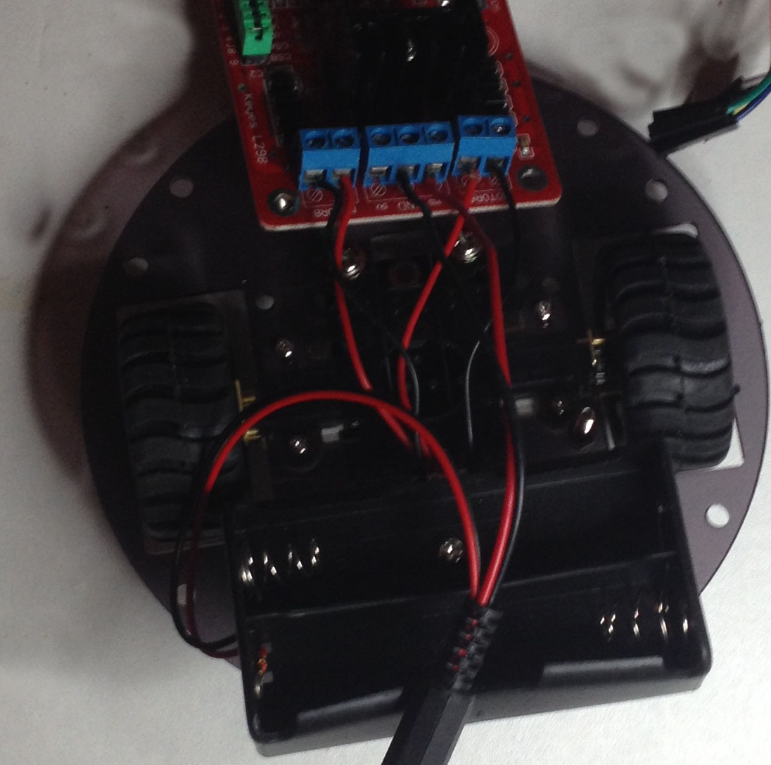
I would advice to first connect the motor controller board with the power lines and the moter wires before mounting the board, my experience is that the wires might be hard to connect when the board is mounted.
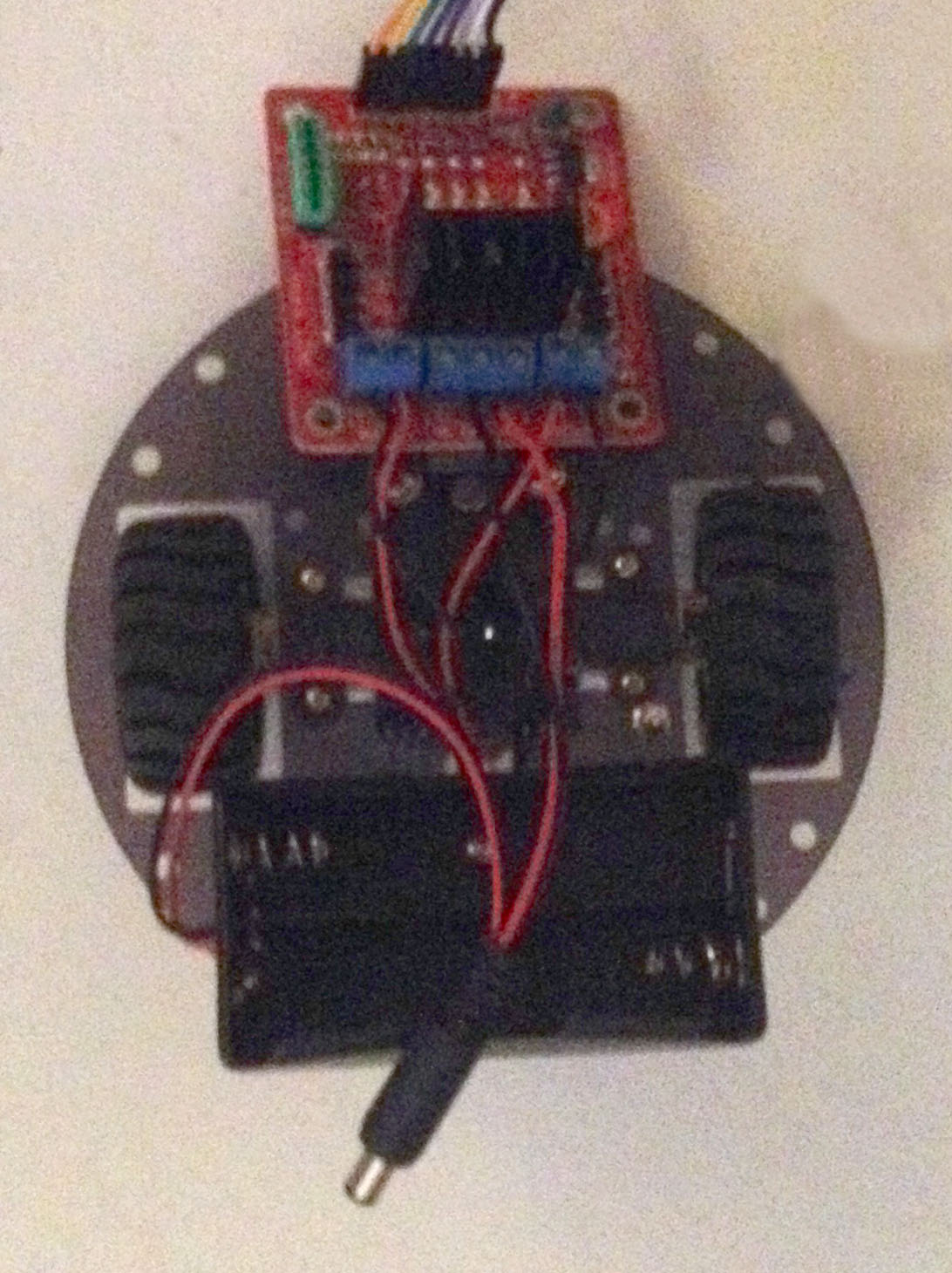
Once the wires are connected, the motor controller board can be mounted onto the 3mm screws using two 3mm nuts.
Then mounted the ball roller at the bottom side of the plate.

Getting this far took me about 1 hour, next episode will start building the rest of this robot kit